Thursday, November 25, 2010

QOS--- Classification

What is Classification ?

Classification direct the traffic to different Forwarding Classes.

Classification can be done in 2 ways

1> Multifield:-  Information on the frame header like Ether type, mac address L3 fields like ip address, prefix and the protocol number , TCP/UDP port number it can also be done on the basis of port numbers and control fields.

The second option it is done on the basis of Behavariol Aggregate

Behavariol Aggregate includes the following:-

Classification can be done on L2, ie traffic which are tagged. In this case the classification is based on dot1p bits. There are 3 bits in user priority which are used for classification, these 2 bits probides 8 different classification levels.


Layer 3 Classification :-

This is done on the basis of Tos bits.


There are two ways to implement this

1> IP precedence which uses the first 3 bits of the Tos field leading to 8 different classes. The next 3 bits can also be used however it increases the sensitivity of the traffic and is not widely used.


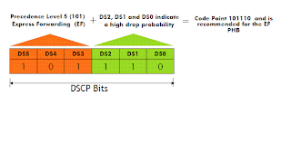
2> DSCP:- 6 bits of the Tos field are used. The first 3 bits are used for precedence and the next 3 bits are used for the drop probability.


The two most important DSCP PHB are

1> Expedited forwarding:- This has a very high  precedence level 5 with a very high drop probability. This can be used in the case for very sensitive traffic like voice. This creates kind of virtual connection between two endpoints.


2> Assured forwarding:- It has different classes as given below:-

In the case of a congested network, the node tries to protect packets with lower drop precedence values, by dropping packets which have a higher drop precedence value.

As we go from left to right in the above table the priority of the packet increases and as we move from top to bottom the drop probability of the packet increases.


MPLS traffic:-

For MPLS traffic exp bits are used to classify the traffic.

Routers can use pipe mode in this case the first 3 DSCP bits are copied to the EXP bits, when the packet enters the MPLS domain, after the exp values are modified inside the mpls domain when the packet egressses the network the exp values are copied back to the exp bits.

In the case of uniform mode the first 3 dscp bits are copied to the exp bits however when the packet egresses out of the network the modified exp bits are stripped off, and the original dscp values are retained.

Classification used in Alcatel routers this is done in the sap ingress policy by default sap ingress policy already exists which is called as 1


The below example gives a snapshot of how the sap ingress policy is applied, as we can notice match dot1p top refers to matching the priority bits with the top tag and bottom refers to matching it with the bottom tag.


Forwarding Class:-

After classification traffic is mapped to different forwarding classes.

As discussed before traffic are classified to 8 different forwarding classes the different FC are given below:-


Mapping of forwarding classes to SAP ingress is shown below:-


QOS

 Quality of service is the ability to provide different priority to different applications, users, or data flows, or to guarantee a certain level of performance to a data flow


When there is no QOS the process implemented is First in First out ie whichever traffic comes in first goes out first.


Congestion occurs when the rate of incoming traffic is more then the rate of egress traffic, congestion leads to delay, jitter and packet loss.


Delay:- Delay is caused by the latency in the network.


Serialization /transmission
􀂃 Queuing delay is the time a packet spends at a queuing point before it is processed or forwarded. Queuing occurs
when the router experiences congestion. Packets may be queued both at the ingress and egress of a router. Queue
delay is proportional to the size of the buffer and is thus variable.
􀂃 Processing delay is the amount of time taken by the router to perform forwarding table lookups, encapsulation,
and any other packet manipulation required, before sending the packet to the egress port.
􀂃 Propagation delay is the time it takes for a packet (signal) to travel across a link (wire) from one router to another.
It is dependent on the characteristics of the transmission media (different media have different propagation
speeds) and the distance between the routers.

Jitter is the variation in the delay

There are two types of Jitter

Positive Jitter

Negative Jitter

Negative jitter signifies that packets are not transmitted out the router at the expected intervals. It can be the result
of significant queuing.
Positive jitter signifies that packets are transmitted “clumped” together, with a smaller than expected intervals
between them. It can result when packets that have been queued together are subsequently transmitted together.


Packet loss
packet corruption (unknown packets are often dropped). It can also result from faulty equipment or signal degradation
on the network media


QOS models:-

There are two services involved

Integrated Services(Inet Serv):- This model is not widely used as it treats each flows separately. This is extremely granular however it increases the load on the nodes. The protocol which is used is RSVP which reserves the resources in each and every node.


.

Wednesday, November 24, 2010

MSTP

MSTP

MSTP, which uses RSTP for rapid convergence, enables VLANs to be grouped into a spanning-tree instance, with each instance having a spanning-tree topology independent of other spanning-tree instances. This architecture provides multiple forwarding paths for data traffic, enables load balancing, and reduces the number of spanning-tree instances required to support a large number of VLANs.


MSTP terminology
􀂃 MSTP ( IEEE 802.1s) runs one instance that contains multiple sub-instances
called MSTI (Multiple Spanning Tree Instance).
􀂃 The CIST is the Common Internal Spanning Tree
• Also known as MSTI 0 (instance 0)
• Exists by default (no configuration needed)
• Automatically manages all vlans 1-4094.
􀂃 When you create MSTI 1 with vlan-range 1-100, then the CIST (MSTI 0)
manages the rest of the vlans (101-4094).
􀂃 With MSTP only one untagged BPDU (null-tag) is sent containing Priority
Info for the CIST and Priority Info for the different MSTIs.

 See the below diagram which provides a representation of MSTP.


MSTP Region:-


MSTP region as a collection of switches, sharing the same view of physical topology partitioning into set of logical topologies. For two switches to become members of the same region, the following attributes must match:
  • Configuration name.
  • Configuration revision number (16 bit value).
  • The table of 4096 elements that map the respective VLANs to STP instance numbers. 

There is no limit to the number of MST regions in a network, but each region can support up to 16 spanning-tree instances. You can assign a VLAN to only one spanning-tree instance at a time.

Significantly reduces the number of STP instances running in the network.

    IST, CIST, and CST

Unlike PVST+ in which all the spanning-tree instances are independent, the MSTP establishes and maintains two types of spanning-trees:
An internal spanning tree (IST), which is the spanning tree that runs in an MST region.
Within each MST region, the MSTP maintains multiple spanning-tree instances. Instance 0 is a special instance for a region, known as the internal spanning tree (IST). All other MST instances are numbered from 1 to 15.
The IST is the only spanning-tree instance that sends and receives BPDUs; all of the other spanning-tree instance information is contained in M-records, which are encapsulated within MSTP BPDUs. Because the MSTP BPDU carries information for all instances, the number of BPDUs that need to be processed by a switch to support multiple spanning-tree instances is significantly reduced. Using TLV’s (Type-Length-Value) those fields carry root priority, designated bridge priority, port priority and root path cost among others.
All MST instances within the same region share the same protocol timers, but each MST instance has its own topology parameters, such as root switch ID, root path cost, and so forth. By default, all VLANs are assigned to the IST.
An MST instance is local to the region; for example, MST instance 1 in region A is independent of MST instance 1 in region B, even if regions A and B are interconnected.

A common and internal spanning tree (CIST), which is a collection of the ISTs in each MST region, and the common spanning tree (CST) that interconnects the MST regions and single spanning trees.


Operations Within an MST Region

The IST connects all the MSTP switches in a region. When the IST converges, the root of the IST becomes the IST master which is the switch within the region with the lowest bridge ID and path cost to the CST root. The IST master also is the CST root if there is only one region within the network. If the CST root is outside the region, one of the MSTP switches at the boundary of the region is selected as the IST master.
When an MSTP switch initializes, it sends BPDUs claiming itself as the root of the CST and the IST master, with both of the path costs to the CST root and to the IST master set to zero. The switch also initializes all of its MST instances and claims to be the root for all of them. If the switch receives superior MST root information (lower bridge ID, lower path cost, and so forth) than currently stored for the port, it relinquishes its claim as the IST master.
During initialization, a region might have many subregions, each with its own IST master. As switches receive superior IST information, they leave their old subregions and join the new subregion that might contain the true IST master. Thus all subregions shrink, except for the one that contains the true IST master.
For correct operation, all switches in the MST region must agree on the same IST master. Therefore, any two switches in the region synchronize their port roles for an MST instance only if they converge to a common IST master.

   Operations Between MST Regions

If there are multiple regions or legacy 802.1D switches within the network, MSTP establishes and maintains the CST, which includes all MST regions and all legacy STP switches in the network. The MST instances combine with the IST at the boundary of the region to become the CST.
The IST connects all the MSTP switches in the region and appears as a subtree in the CST that encompasses the entire switched domain, with the root of the subtree being the IST master. The MST region appears as a virtual switch to adjacent STP switches and MST regions.
The above figure shows a network with three MST regions and a legacy 802.1D switch (D). The IST master for region 1 (A) is also the CST root. The IST master for region 2 (B) and the IST master for region 3 (C) are the roots for their respective subtrees within the CST. The RSTP runs in all regions.

As mentioned before, every MSTP region runs special instance of spanning-tree known as IST or Internal Spanning Tree (=MSTI0). This instance mainly serves the purpose of disseminating STP topology information for MSTIs. IST has a root bridge, elected based on the lowest Bridge ID (Bridge Priority + MAC address). The situation changes with multiple MSTP regions in the network. When a switch detects BPDU messages sourced from another region (or STP/PVST+ BPDU), it marks the corresponding port as MSTP boundary. For the convenience, we would call all other ports as “internal”. A switch that has boundary ports is known as boundary switch.
On the figure below you can see three MSTP regions interconnected in “ring” topology using pair of links between every pair of regions. The links connecting the regions connect the boundary ports. Since every switch has a connection to some other region, all switches are boundary. Notice the simplified notation for link costs and bridge priorities. We will use those to demonstrate how the CIST is constructed. For the simplicity, assume that all link costs inside the region are the same value of 1.


To see how this is accomplished, first have a look at the structure of MSTP BPDU. On the figure below, notice MSTP uses protocol version 3 as opposed to RSTP’s version 2. Version 4 is reserved to SPT – Shortest Path Tree – new loop prevention and packet bridging standard defined in emerging IEEE 802.1aq document.


The MSTP BPDU contains two important block of information. One, highlighted in red, is related to CIST Root and CIST Regional Root election. As you will see later, CIST Root is elected among all regions and CIST Regional Root is elected in every region. The green block outlines the information about CIST Regional Root (which becomes the IST Root in presence of multiple regions). The CIST Internal Root path cost is the intra-region cost to reach the CIST Regional Root. It is important to keep in mind that IST Root = CIST Regional Root in case where multiple regions interoperate. This transformation is explained further in the text. Now, to define the CIST Root and CIST Regional Root roles:
  • CIST Root is the bridge that has the lowest Bridge ID among ALL regions. This could be a bridge inside a region or a boundary switch in a region.
  • CIST Regional Root is a boundary switch elected for every region based on the shortest external path cost to reach the CIST Root. Path cost is calculated based on costs of the links connecting the regions, excluding the internal regional paths. CIST Regional Root becomes the root of the IST for the given region as well. 

CIST Root Bridges Election Process

  • When a switch boots up, it declares itself as CIST Root and CIST Regional Root and announces this fact in outgoing BPDUs. The switch will adjust its decision upon reception of better information and continue advertising the best known CIST Root and CIST Regional Root on all internal ports. On the boundary ports, the switch advertises only the CIST Root Bridge ID and CIST External Root Path Cost thus hiding the details of the region’s internal topology.
  • CIST External Root Path Cost is the cost to reach the CIST Root across the links connecting the boundary ports – i.e. the inter-region links. When a BPDU is received on an internal port, this cost is not changed. When a BPDU is received on a boundary port, this cost is adjusted based on the receiving boundary port cost. In result, the CIST External Root Path Cost is propagated unmodified inside any region.
  • Only a boundary switch could be elected as the CIST Regional Root, and this is the switch with the lowest cost to reach the CIST Root. If a boundary switch hears better CIST External Root Path cost received on its internal link, it will relinquish its role of CIST Regional Root and start announcing the new metric out of its boundary ports.
  • Every boundary switch needs to properly block its boundary ports. If the switch is a CIST Regional Root, it elects one of the boundary ports as the “CIST Root port” and blocks all other boundary ports. If a boundary switch is not the CIST Regional Root, it will mark the boundary ports as CIST Designated or Alternate. The boundary port on a non regional-root bridge becomes designated only if it has superior information for the CIST Root: better External Root Path cost or if the costs are equal better CIST Regional Root Bridge ID. This follows the normal rules of STP process.
  • As a result of CIST construction, every region will have one switch having single port unblocked in the direction of the CIST Root. This switch is the CIST Regional Root. All boundary switches will advertise the region’s CIST Regional Root Bridge ID out of their non-blocking boundary ports. From the outside perspective, the whole region will look like a single virtual bridge with the Bridge ID = CIST Regional Root ID and single root port elected on the CIST Regional Root switch.
  • The region that contains the CIST Root will have all boundary ports unblocked and marked as CIST designated ports. Effectively the region would look like a virtual root bridge with the Bridge ID equal to CIST Root and all ports being designated. Notice that the region with CIST Root has CIST Regional Root equal to CIST Root as they share the same lowest bridge priority value across all regions.
Have a look at the diagram below. It demonstrates the CIST topology calculated from the physical topology we outlined above. First, SW1-1 is elected as the CIST Root as it has the lowest Bridge ID among all bridges in all regions. This automatically makes region 1 a virtual bridge with all boundary ports unblocked. Next, SW2-1 and SW3-1 are elected as the CIST Regional Roots in their respective regions. Notice that SW3-1 and SW2-3 have equal External Costs to reach the CIST Root but SW3-1 wins the CIST Regional Root role due to lower priority. Keep in mind that in the topology with multiple MSTP regions, every region that does not contain the CIST Root has to change the IST Root election process and make IST Root equal to CIST Regional Root.


Lag and its different variations

Lag increases the bandwidth between two nodes by grouping different ports together.

Increases performance as the load can be shared between the two links.

Also provides improved resiliency as the traffic can be switched from one port to another in the event of a failure of one of the ports.


Lags can be configured on both the access and the network ports. The speed and duplex settings of all the ports in the lag should match, autonegotiation should be disabled or should be configured as limited.

For 10 gig ports the X-GIG setting of the ports should be same.

Threshold action when down is specified the lag will be brought down only when the number of links active falls below the thresold.
ie if the threshold configured is 4, so the lag will be brought down when the number of active links in the lag is 4, the lag is up when the number of links is 5.

Dynamic Cost:- If the cost of the link is 100, and if we bundle 4 links the cost od the lag will be 25 and then if one of the link goes down the cost will 100/3=33 approx.

Configured address/Hardware Address;- The first 3 bits match the first 3 bits of the chassis mac address the last 3 bits resembles the lag number so if the lag used is 1 it should be 00:01:41.

Lacp

Lag can also be configured by using a protocol such as LACP.
These LACP messages every 1 sec if lacp is configured as fast or every 30 sec if lacp is configured as a slow.
Uses slow protocol destination mac 01:80:C2:00:00:02
Self is known as the actor and the peer is known as the partner.

Three parameters uniquely identify a LAG instance to the
local node:
􀁹
subsequent LAGs)
LACP key (default 32768 for first LAG, increase by one for
􀁹
System ID (derived from base MAC address; show chassis)
􀁹
x


Passive will only start sending lacp packets once it starts receiving from the active side.
System priority (default 32768; configure system lacp-systempriority)