Router 1 LSA:-
This includes all the active interfaces of the router, and are advertised within an area only.
Advertises with the ip-prefix/masks assigned to that link.
Link state ID is the advertising routers RID.
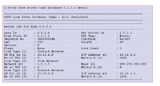
This is how a Router LSA looks like:-
LS Age ― Gives the time, in seconds, since the LSA originated. The LSA age is used when a router wants to flush
a self-originated LSA from the area databases. It does this by prematurely “aging out” the LSA; that is, setting
the age of the LSA to MaxAge and then flooding the LSA. Receiving routers, seeing the MaxAge value, do a direct
acknowledgment and immediately reflood the LSA.
Options ― Represents the optional capabilities supported by the router, such as option E that is used to indicate
the originating router area type; when set, it indicates whether the originating area is a backbone, transit or
non-stub area.
LS Type ― Represents the types of LSA
LSA ID ― Defines the identity of the link-state
LS Sequence Number ― Detects old or duplicate LSAs
LS Checksum ― Performs checksum on the LSA, not including LS age. An LSA can be corrupted during flooding or
while kept in the memory, so this checksum is necessary. This field cannot have a value of 0 because 0 means
that the checksum has not been performed. The checksum is performed at the time of LSA generation or when
the LSA is received
Length ― Includes the length of the LSA, including the 20-byte header
Bit V — This bit is used to determine whether it is an endpoint of a virtual link.
Bit E — This bit is used to determine whether this router is an Autonomous System Boundary Router (ASBR).
Notice that this is different from the option E bit, discussed in the previous slide.
Bit B — This bit is used to determine whether this router is an Area Border Router (ABR).
Number of Links — This includes the number of router links. Note that the router LSA includes all of the router
links in a single LSA for an area.
Link ID, Link Data, and Type — The Type field represents the four types of router links. The other two fields,
Link ID and Link Data, represent the 4-byte IP address value, depending on the network type. For links to transit
networks, numbered point-to-point links, and virtual links, the link data field contains the IP interface address
of the associated router interface. For links to stub networks, the field contains the stub network's IP address
mask. For unnumbered point-to-point links, the link data field is set to the unnumbered interface's ifIndex value.
ToS and ToS Metric — These fields represents the type of service and are normally set to 0.
Metric — This field contains the OSPF cost of using a specific link. This is a configurable value. Stub networks
can have a cost of 0. All other networks must have a cost of nonzero.
If a router in area 1 wants to generate a router LSA for area 1:
The router examines its interfaces.
If the link does not belong to area 1, the link is not added to the router LSA.
If the link is down, the link is not added to the router LSA.
If the interface is a loopback, a type 3 link (stub network) is added, as long as this is not an interface to an
unnumbered point-to-point network. The link ID is set to the IP interface address, the link data field is set
to the mask /32 (indicating a host route), and the cost is set to 0.
Suppose if there are 6 routers in the area hence the number of Router LSA that will be present in the database is 6.
Type 1 (router) LSA for rtr1 in Area 0:X Link State ID is set to RID 1.1.1.1.X Number of links is 3: the system interface, interface to-rtr1, and interface to-rtr3.X The interface type between the routers is broadcast.Description of the link between rtr1 and rtr2:X There is an adjacency; therefore, add a type 2 (transit network) link.X Link ID is set to the IP address of the DR (10.10.2.2).X
responsible for generating type 2 (network) LSAs.The link data field is set to the router’s own address (10.10.2.2); rtr1 is the DR for this network and isX The cost is equal to 1000.Description of the system interface:X This is a loopback interface; therefore, add a type 3 (stub network) link.X Link ID is set to the IP interface address (1.1.1.1).X The link data field is the IP interface subnet mask (255.255.255.255).X The cost is set to 0.Description of the link between rtr1 and rtr3:X There is an adjacency; therefore, add a type 2 (transit network) link.X Link ID is set to the IP address of the DR (10.10.3.2).X
responsible for generating type 2 (network) LSAs.The link data field is set to the router’s own address (10.10.3.1); rtr3 is the DR for this network and isX
Routers in a stub area do not have this value set.
Recall that options value E indicates that the originating router is in a backbone, transit, or non stub area.
Type 2 Network LSA:-
One LSA for each broadcast or NBMA network in an area
P
X
X
the area
The DR for the network originates the LSA. The DR originates the LSA only if it is fully adjacent to at least one
other router in the network. The network LSA is flooded throughout the area that contains the transit network,
and no further. The network LSA lists those routers that are fully adjacent to the DR; each fully adjacent router
is identified by its OSPF RID. The DR includes itself in this list.
The link-state ID for a network LSA is the IP interface address of the DR. This value, masked by the network's
address mask (which is also contained in the network LSA) yields the network's IP address.Flooded within the area only; becomes a type 3 LSA when exitingAdvertised by the DRLists the subnet mask of the link and all attached routers
The network LSA has two important components:X Network mask field• The IP address mask for the network. For example, a class A network has the mask /8.X Attached router field•
the DR are listed. The DR includes itself in the list. The number of routers included can be deduced
from the LSA header's length field.
No metric field in Network LSA as the cost of the links are assumed to be 0. The RIDs of all routers attached to the network. Actually, only those routers that are fully adjacent to
rtr1 Type 2 (network) LSA for network 10.10.2.0/30X rtr1 is the DR for this segment and is therefore responsible for generating the network LSA.X Link-state ID is set to the DR’s IP address.X Network mask is set to the IP address mask 255.255.255.252.X The network LSA also contains the number of adjacent routers and lists the RID of each router.X The number of adjacent routers on this segment is 2.X The RIDs are 1.1.1.1 and 2.2.2.2.X
There are no Type 2 LSA's that are generated if the network is configured as Point to Point.
The needs for multiple areas:-
An area is a logical collection of OSPF networks,
routers, and links that have the same area identification. A router within an area must maintain a topological
database for the area to which it belongs. The router does not have detailed information about network
topology outside of its area, thus the size of its database is reduced.
It is not possible to do route update filtering within an
area. The link-state database (LSDB) of routers within the same area must be synchronized and be exactly the
same; however, route summarization is possible between different areas. The main benefit of creating areas is a
reduction in the number of routes to propagate by the summarization of routes.
Backbone area must never be divided in any scenarios.The route is derived from the link-state ID and the network mask.Scalability issues exist for link-state networks:P
the size of the network.The size of the link-state database increases exponentially withP
exponentially.The complexity of the SPF calculation also increasesP
forwarding table on every router.A topology change requires a complete recalculation of theX
several smaller routing domains, called Areas.OSPF hierarchy allows a large routing domain to be split intoX
If frequent topology changes occurs the folloding will be confined to a particular area only.
There are 3 different types of areas in ospf:-Area hierarchy results in suboptimal routing.Backbone area
The OSPF backbone area, area 0.0.0.0, must be contiguous and all other areas must be connected to it. The
backbone distributes routing information among areas. If it is not practical to connect an area to the backbone,
the ABRs must be connected via a
Stub areaA stub area is a designated area that does not allow external route advertisements. Routers in a stub area do
not maintain external routes. A single default route to an ABR replaces all external routes. This OSPF
implementation supports the optional summary route (type 3) advertisement suppression from other areas into a
stub area. This feature further reduces topological database sizes as well as OSPF protocol traffic, memory
usage, and CPU route-calculation time.
NSSA
Another OSPF area type is called an NSSA. NSSAs are similar to stub areas in that no external routes are
imported into the area from other OSPF areas. External routes learned by OSPF routers in the NSSA are
advertised as type 7 LSAs within the NSSA area and are translated by ABRs into type 5 external route
advertisements for distribution into other areas of the OSPF domain. An NSSA cannot be designated as the
transit area of a virtual link.virtual link.
Stub area and totally stubby area:-
Stub area
A stub area is a designated area that does not allow external route advertisements. Routers in a stub area do
not maintain external routes. A single default route to an ABR replaces all external routes. This OSPF
implementation supports the optional summary route (type 3) advertisement suppression from other areas into a
stub area. This feature further reduces topological database sizes as well as OSPF protocol traffic, memory
usage, and CPU route-calculation time.
Stub areas must conform to the following attributes:X
within Area 2. Traffic would not pass through Area 2 to get to any other location.The area must be a dead end. In the example above, the only reason to enter Area 2 is to access networksX Virtual links are not supported.X
However, type 3 LSAs are still advertised.
Stub area, no summary must conform to the following attributes:Type 4 and type 5 LSAs are blocked by the ABR, and a default route is advertised instead into the area.X All attributes of a stub area are the same.X
ABR originates a type 3 LSA into the stub area. The link-state ID is 0.0.0.0, and the network mask is set to
0.0.0.0.By adding "no summary", the ABR blocks type 3, 4 and 5 LSAs; instead it advertises a default route. TheX The industry term is "totally stubby".
NSSA:-NSSAs (like stub areas) must be placed at the edge of an OSPF routing domain. NSSAs
are more flexible than stub areas in that an NSSA can import external routes into the OSPF routing domain,
thereby providing transit service to small routing domains that are not part of the OSPF routing domain.
LSA used within the multiple areas:-
LSA type 3:-Floods summary network information to other areasX States the network number and maskX Advertised by the originating area ABRX Goes to all areas within the autonomous system
When summarization is configured, a summary LSA is generated with the link-state ID set to the range’s address.
The metric is set to the highest cost of the component networks.Advertises the location of the ASBR to all other areas in the AS
LSA type 4:-X Generated by the ABR of the originating areaX
areaThe ABR for the next area initiates another type 4 LSA for thatX Flooded throughout the areaX
Contains the RID of the ASBR only
A type 4 LSA is only sent from the ABR when a type 5 is generated by the ASBR and sent to the ABR.
The ABR for the next area will initiate another type 4 LSA for that area.
Stub area and stub no summary:-Stub areas must conform to the following attributes:X
within Area 2. Traffic would not pass through Area 2 to get to any other location.The area must be a dead end. In the example above, the only reason to enter Area 2 is to access networksX Virtual links are not supported.X
However, type 3 LSAs are still advertised.
Stub area, no summary must conform to the following attributes:Type 4 and type 5 LSAs are blocked by the ABR, and a default route is advertised instead into the area.X All attributes of a stub area are the same.X
ABR originates a type 3 LSA into the stub area. The link-state ID is 0.0.0.0, and the network mask is set to
0.0.0.0.By adding "no summary", the ABR blocks type 3, 4, and 5 LSAs; instead, it advertises a default route. TheX The industry term is "totally stubby".
LSAType 5
LSA Type 5:-The link-state ID is set to the destination network’s IP address.
The Network mask is set to the advertised network mask.
There are 2 types of metrics that can be advertised:X
considered larger than any link-state path.If the E bit is set, the metric specified is a type 2 (external) metric. This means that the metric isX
expressed in the same units as the link-state metric.
Forwarding Address: Indicates the address to which data traffic to the advertised network should be forwarded.
If the value is set to 0.0.0.0, this means that the traffic should be forwarded to the ASBR.
The external route tag is a 32-bit value assigned to the external route. It is not used by OSPF itself. The tag can
be used to communicate information between ASBRsIf the E bit is not set, the metric specified is a type 1 (external) metric. This means that the metric is
If the E bit is not set, the metric specified is a type 1 (external) metric. This means that the metric is
Type 7 (NSSA) LSAs are only advertised within the NSSA area. They are generated by the advertising ASBR and
identify the external networks that are being redistributed into OSPF.
At the NSSA area’s ABR, all type 7 LSAs are converted into type 5 LSAs as they are advertised into the rest of the
OSPF autonomous system. Because the Type 5 LSA is originated by the ABR, no Type 4 LSA is required.
NSSA areas are treated just like stub areas by the ABR. However, they are not dead ends because traffic can
traverse the NSSA to access a non-OSPF part of the network.


